
Frequency Range900MHz
TechnologyGSM
Output Power30/.../43±2dBm (Customized)
Maximum Gain80/.../95±3dB(Customized)
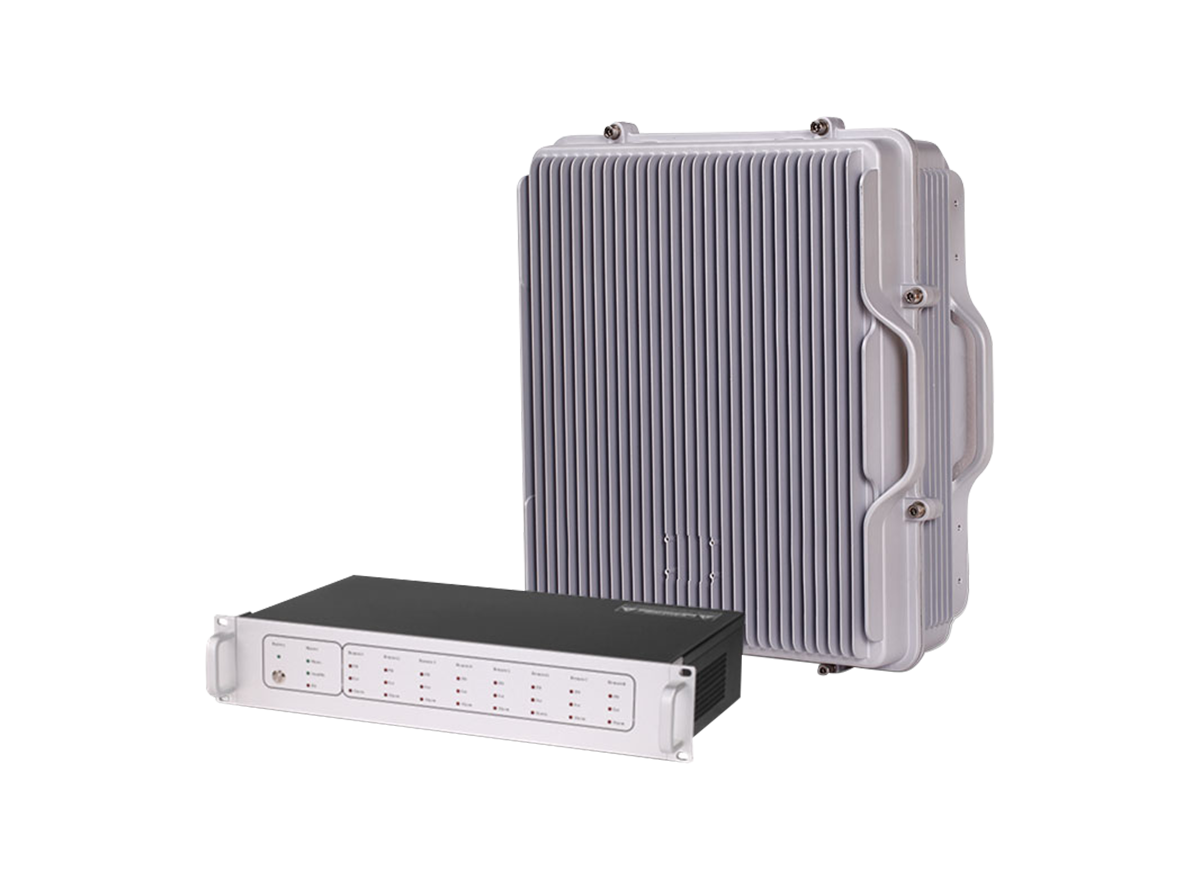
The GSM Fiber Optic Repeater (FOR) is designed to solve problems of weak mobile signal in the place that is far away from the Base Transceiver Station (BTS) and has fiber optic cable network underground.
The system consists of two parts: Donor Unit and Remote Unit. The Donor unit captures the BTS signal via direct coupler closed to BTS, then converts it into optic signal and transmits the amplified signal to the Remote Unit via fiber optic cable. The Remote unit will reconvert the optic signal into RF signal and provide the signal to the areas where network coverage is inadequate. And the mobile signal is also amplified and retransmitted to the BTS via the opposite direction.
1. Aluminum-alloy casing with IP65 protection has high resistance to dust, water and corroding.
2. Supporting 5G/4G/3G/2G system.
3. Tx/Rx control and alarm messages to be transmitted via one fiber optic cable.
4. Adopting WDM module to realize long-distance transmission.
5. Stable and improved signal transmission quality.
6. One MU supporting up to 4 RUs to maximize utilization of fiber optic cable.
7. RJ45 port provides a link to a notebook for local supervision or IP Based NMS(Network Management System) that can remotely supervise repeater's working status and download operational parameters to the repeater Via Ethernet or LAN
 | 1. To expand signal coverage or fill signal blind area where signal is weak or unavailable. 2. Outdoor: Airports, tourism regions, golf courses, tunnels, factories, mining districts, villages, … 3. Indoor: Hotels, exhibition centers, basements, shopping malls, offices, parking lots, … |
| ltems | MU | Ru | |
| 5G/4G/3G/2G | |||
| Frequency Range | Uplink | 1710~1785MHz&1920~1980MHz | |
| Downlink | 1805~1880MHz&2110~2170MHz | ||
| Transmission Distance | ≤20km | ||
| Maximum Input Power(Non-Destructive) | 10dBm | ||
| Maximum RF Output Power(Downlink) | 30/ .../43±2dBmper Band(Customized) | ||
| Maximum Gain(Cable Access) | 45/...55±3dB(MU+RU) | ||
| Gain Adjustment Range | 0~30 dB @ Step of 1 dB | ||
| VSWR | ≤1.5 | ||
| Noise Figure@1Ru Connection | ≤5dB | ||
| Gain Flatness | ≤±3dB | ||
| Standard | Complies with 3GPP and ETSI | ||
| Spurious Emission | 9kHz~1GHz: ≤ -36dBm/30kHz | ||
| 1GHz~12.75GHz: ≤ -30dBmV30kHz | |||
| System Delay | ≤ 5us | ||
| I/O lmpedance | 50Ω | ||
| RF Connector | 2XN-Female for MU,N-Female for RU | ||
| Optical Connector | 4X FC/APC for MU,1 × LC/UPC for RU | ||
| Fiber Optical Type | Single Mode | ||
| Optical Output Power | 0±3dBm(1310nm)/ -3±3dBm(1550nm) | ||
| Optical Receiver Sensitivity | ≥-15dBm | ||
| Temperature Range | -25℃~+ 55℃ | ||
| Relative Humidity Range | ≤95%(Non Condensing) | ||
| Power Supply(Customized) | DC-48V or AC220V, 50/60Hz | ||
| Dimensions | 483mm x 223mm x 90mm | 500mm x 440mm x 187mm | |
| Weight | ≤8kg | ≤25 kg | |
| Application | lndoor(IP30) | lndoor or Outdoor(IP65) | |
| Local Control | Web Browser GUI Local Via RJ-45 Interface or WiFi Hotspot | ||
| NMS Mode(Optional) | Wireless Modem (3G/4G), IP Connectivity | ||
| NMS Function(Optional) | Real-time Aarm for Door Status,Temperature, Power Supply, VSWR, etc; Remote Control Such as Turn On/Off, Increasing/Decreasing Output Power etc; Real-time Status for Output/Input Power, UL/DL Gain, AlI Status of Repeater etc. | ||