
Frequency Range390~395 MHz
TechnologyTETRA
Output Power30/.../43±2dBm (Customized)
Maximum Gain80/.../95±3dB(Customized)
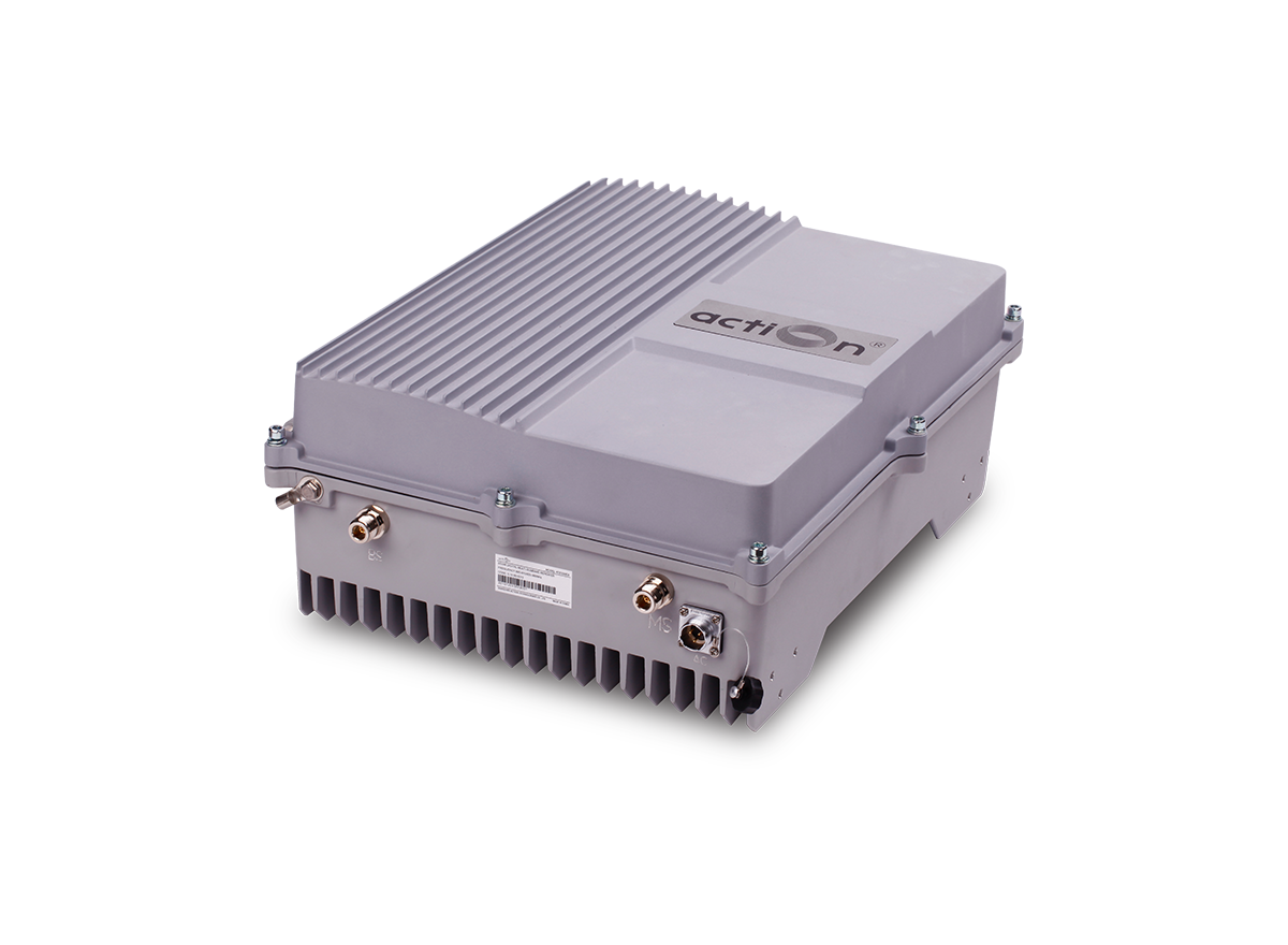
The TETRA RF BDA is designed to provide a more cost-effective solution than adding a new Base Transceiver Station (BTS) to improve signal coverage and communication quality in TETRA system. And its easy installation and maintenance can help carrier get fast return.
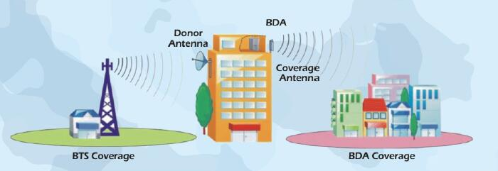
The BDA is working as a relay between the BTS and mobiles. It receives the low-power signal from BTS via the Donor Antenna, linearly amplifies the signal and then retransmits it via the Coverage Antenna to the weak/blind coverage area. And the mobile signal is also amplified and retransmitted to the BTS via the opposite direction.
The band-selective function can amplify all signals in the whole band (bandwidth is customized).
1. Aluminum-alloy casing with IP65 protection for high resistance to dust, water and corrosion.
2. Supporting TETRA/DMR/P25/iDEN system.
3. Low interference to BTS by adopting linear amplifier with high gain and low noise.
4. Adopting filter with highly selectivity and low insertion loss eliminates interference between uplink and downlink.
5. RJ45 port provides a link to a notebook for local supervision or IP Based NMS (Network Management System) that can remotely supervise BDA’s working status and download operational parameters to the BDA Via Ethernet or LAN.
 | To expand signal coverage or fill signal blind area where BTS signal is weak or unavailable. 1. Public Safety 2. Transportation 3. Utilities 4. Government 5. Military 6. PAMR 7. Commercial & Industry 8. Oil & Gas |
| ITEMS | SPECIFICATIONS | |
Frequency Range (Customized) | Uplink | Downlink |
380~385MHz/ 415~420MHz/ 806~821MHz | 390~395MHz/ 425~430MHz/ 851~866MHz | |
| Bandwidth(To Specify Before Production) | From 1 to 15MHz, Filter SAW Adjusted | |
| Maximum Gain(Customized) | 85±3dB | 85/.…./90±3dB |
| Maximum Output Power(Customized) | 30±2dBm | 30/.../43±2dBm |
| ln-Band Fatness | ≤±2.5dB | |
| ALC(Auto Level Control) | ≤2dB(When The Maximum Output Power of BDA is Reached, lncrease Input Power by 1~20dbm, Output Variation ≤2dB) | |
| Noise Figure | ≤5dB | |
| Gain Adjustment Range | 1~31 dB @Step of 1 dB | |
| VSWR | ≤1.5 | |
| System Delay | ≤5uSec | |
| Spurious Emission | 9KHz-1GHz:≤-36dBm/30KHz | |
| 1GHz-12.75GHz:≤-30dBm/30KHz | ||
| Third-Order lnter-Modulation | ≤-45dBc | |
| Output/Input Resistance | 50Ω | |
| RF Connector | N-Type (Female) | |
| Working Temperature | -25℃~+55°C | |
| Relative Humidity Range | ≤95% (Non Condensing) | |
| Power Supply | AC220V, 50/60Hz | |
| Dimensions | 428mmx328mm×175mm | |
| Weight | 15kg | |
| Application | lndoor or Outdoor(IP65) | |
| Local Control | Web Browser GUI Local Via RJ-45 Interface or WiFi Hotspot | |
| NMS Mode(Optional) | Wirelss Modem(3G/4G). IP Connectivity | |
| NMS Function(Optional) | Real-time Alarn for Door Status, Temperature, Power Supply, VSWR etc; Remote Control Such as Turn On/Off, Increasing/Decreasing Output Power etc; Realtime Status for Output/Input Power, UL/DL Gain,All Status of BDA etc. | |